- Home
- Company
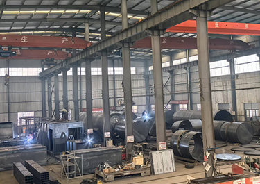 Our FactoryWe have a team of over 30 talented mobile fuel station R&D experts, as well as a 50,000-square-meter advanced modern intelligent manufacturing plant.
 - Mobile Fuel Station
- Storage Tank
- Blog
- Contacts


- Description
A fuel storage tank with a dispenser is a complete system integrating storage and dispensing of fuel, commonly found in gas stations, industrial and mining enterprises, and logistics parks. It typically consists of two main parts: an underground or above-ground fuel storage tank and a smart fuel dispenser, tightly connected by a complex piping and electrical system.


1. Core Components and Functions (Structured List)
1.1. Oil Storage Tank Unit (Core Oil Storage Carrier)
| Components | Core Parameters/Specifications | Key Functions | Compliance Points |
| Main Tank | Primarily horizontal; common single tank size 10–50 m³ (skid-mounted ≤50 m³, urban areas ≤20 m³); double-layer structure (SS/SF/FF) | Safe oil storage, reduced evaporation loss | Buried preferred; double-layer tanks must be equipped with leak detection |
| Compartment Structure | Single tank >25 m³ requires compartment (≤25 m³); urban areas >10 m³ requires compartment (≤10 m³) | Limits risk range, improves explosion resistance | Mandatory requirement of AQ/T 3002-2021 |
| Manhole | Diameter 500–600 mm, with pressure cap and seal | Installation, cleaning, and maintenance access | Fireproof gasket, normally closed seal |
| Inlet/Outlet Pipes | Inlet pipe extends 50–100 mm to the bottom of the tank; outlet pipe is approximately 150 mm from the bottom of the tank | For unloading and supplying oil, prevent siphoning and splashing | Inlet is at the top, higher than the highest liquid level |
| Measuring Port | With aluminum guide groove, normally closed | Manual measurement of oil level and temperature | Guide groove with lower gauge to prevent gauge oscillation error |
1.2. Refueling Unit (Transportation and Metering Core)
| Components | Core Parameters/Specifications | Key Functions | Compliance Requirements |
| Explosion-proof Pump | Vane pump/submersible pump; explosion-proof rating Ex dⅡBT4 | Pumps oil from the tank to the refueling machine | The skid-mounted compartment must be ventilated and equipped with gas detection |
| Flow Meter | Volumetric/mass type; accuracy ±0.2%–±0.3% | Precisely measures oil volume | Regularly calibrated, data transmitted to display screen in real time |
| Fueling nozzle | Self-sealing; gasoline nozzle ≤50 L/min, diesel nozzle 80–90 L/min | Refueling, prevents overflow | Gasoline nozzle must be self-sealing, hose equipped with safety breakaway valve |
| Hoses and breakaway valve | Oil-resistant rubber; breakaway valve with moderate disconnection pressure | Connects nozzle to body, seals in case of accidental breakage | Breakaway valve automatically seals at both ends, no leakage |
| Display and control system | Electronic display screen; IC card/QR code payment module | Displays amount, volume, controls start/stop | Explosion-proof design, data can be uploaded to management system |
1.3. Process piping unit (transport network)
- Unloading system: Unloading hose, self-closing quick connector, unloading valve; prevents unloading leakage, skid-mounted requires self-closing connector.
- Fuel Supply System: Fuel outlet pipe, filter, high-temperature automatic fuel shut-off valve (fusible link); automatically shuts off the fuel supply when the fuel temperature is too high, protecting the system.
- Vapor Recovery System (required for gasoline): Recovery pipe, vacuum pump, vapor separator; recovers vapors volatilized from the vehicle's fuel tank into the reservoir, reducing pollution and loss.
- Pipeline Protection: Buried pipelines use seamless steel pipes with reinforced corrosion protection (e.g., "five layers of oil and three layers of cloth," thickness ≥ 5.5 mm); anti-buoyancy supports are installed to prevent the pipeline from cracking due to groundwater buoyancy.
1.4. Safety Protection Unit (Compliance Core)
| Protection Category | Key Components | Triggering Conditions/Functions | Standards |
| Breathing and Flame Arrestor | Mechanical Breathing Valve, Flame Arrestor Cap | Controls tank pressure to prevent flame entry | GB 50156-2021 |
| Overflow Control | High Level Alarm (90% level), Anti-Overflow Valve (95% level) | Alarm and automatically stops oil supply | GB 50156-2021 6.4.5 |
| Emergency Pressure Relief | Emergency Pressure Relief Valve/Safety Valve | Relieves pressure when tank is over-pressurized to prevent tank rupture | AQ/T 3002-2021 |
| Fire Protection Facilities | Portable Dry Powder Fire Extinguisher, Automatic Fire Extinguisher (above the fuel dispenser) | Extinguishes initial fires; automatic activation temperature ≤95℃ | GB 50156-2021 6.4.7 |
| Leak Detection | Double-walled Tank Gap Detector, Pipeline Leak Alarm | Real-time Monitoring of Inner Tank or Pipeline Leaks | SH/T 3134-2023 |
1.5. Instrument Control Unit (Intelligent Monitoring)
- Level Gauge: Magnetostrictive/Radar type; real-time monitoring of liquid level, temperature, and volume, outputting a high-level alarm signal.
- Pressure/Temperature Sensor: Monitors tank pressure and oil temperature, linking the pressure relief valve and high-temperature shut-off valve.
- Gas Detector: Installed below the fuel dispenser, in the unloading area, and in the skid-mounted operating compartment; detects oil and gas concentration, alarming and cutting off power when levels exceed limits.
- PLC Control Cabinet: Integrates control of pumps, valves, and alarm systems, enabling automatic start/stop and emergency shut-off; standard configuration for skid-mounted units.
1.6. Oil and Gas Recovery System
To reduce environmental pollution and safety hazards caused by oil and gas volatilization, modern refueling systems generally include oil and gas recovery functionality.
- Unloading Vapor Recovery (Primary Recovery): When a tanker truck unloads oil into a storage tank, the vapors displaced from the storage tank are recovered into the tanker truck through a closed pipeline and transported back to the oil depot for processing.
- Refueling Vapor Recovery (Secondary Recovery): When you refuel your vehicle, the fuel nozzle simultaneously draws the vapors evaporating from the fuel tank into the fuel dispenser and recovers them through another pipeline into the underground storage tank.
1.7. Basic Ancillary Facilities
- Foundation and Buoyancy Resistance: Concrete foundation, flat steel to secure the tank; ensuring the tank weight + foundation weight > groundwater buoyancy.
- Leakage Prevention Measures: Double-walled tank or single-walled tank + leak-proof tank pool; preventing oil leakage and contamination of soil and groundwater.
- Operation Cabin (Skid-Mounted Dedicated): Steel structure explosion-proof cabin, with ventilation, lighting, and explosion-proof electrical distribution box; integrating fuel dispenser, pump, and control cabinet.
2. Key Technical Parameters and Compliance Boundaries (Quantitative Indicators)
2.1. Tank Material and Structure
- Buried Tanks: Double-walled tanks are preferred (SS double-walled steel, SF inner steel outer fiberglass, FF double-walled fiberglass); single-walled tanks must be equipped with a leak-proof tank pool.
- Skid-mounted Tanks: Forced double-walled steel construction, with leakage detection at the gap; inner tank design pressure ≥ 0.8 MPa, outer tank atmospheric pressure.
2.2. Volume Limitations
- Conventional Station Buried Tanks: Single tank ≤ 50 m³, total volume ≤ 150 m³ (calculated separately for gasoline and diesel).
- Skid-mounted Units: Above-ground single tank ≤ 50 m³ (≤ 20 m³ in urban areas); single tank > 25 m³ requires a compartment (> 10 m³ in urban areas requires a compartment).
2.3. Fuel Nozzle Flow Rate
- Gasoline Nozzle: ≤ 50 L/min (self-sealing, anti-overflow); Diesel Nozzle: 80–90 L/min (suitable for large vehicles). 2.4. Explosion-proof and Corrosion-proof.
- Explosion-proof rating: Ex dⅡBT4 (applicable to Class IIB flammable liquids such as gasoline and diesel).
- Corrosion-proof requirements: Buried steel tanks and pipelines use reinforced anti-corrosion coatings with a thickness ≥ 5.5 mm; coating adhesion meets standards, with no pinholes or peeling.


3. Working Principle:
Let's look at a typical refueling process through the complete journey of a refueling machine:
- 3.1. Start-up command: You lift the fuel nozzle, and the signal is transmitted to the computer device inside the fuel dispenser.
- 3.2. Power output: The computer immediately starts the explosion-proof motor (or starts the submersible pump in the fuel tank).
- 3.3. Fuel delivery: The fuel pump starts working, drawing fuel from the storage tank (or being pushed up by the submersible pump).
- 3.4. Fuel-gas separation: The fuel enters the fuel-gas separator, which removes any mixed gases, ensuring accurate metering.
- 3.5. Precise Measurement: Pure oil flows through the flow meter, driving its internal mechanical structure to rotate. An encoder connected to the flow meter converts the rotation into electrical pulse signals, which are continuously sent to the computer. The computer calculates the amount of oil dispensed based on the number of pulses and simultaneously updates the display screen with the liters and amount.
- 3.6. Safe Refilling: The oil is finally injected into your fuel tank through a self-sealing nozzle. Refilling stops when the tank is full or when you release the nozzle trigger. The computer records the refilling data.
4. Comparison of Two Mainstream Forms (Buried Station vs. Skid-Mounted Unit)
| Comparison Items | Conventional Buried Gas Station | Skid-Mounted Gas Station |
| Installation Method | Tank buried underground, fuel dispenser above ground | Tank, fuel dispenser, and pipeline integrated on a steel skid, placed on the ground |
| Approval Difficulty | Complex process, requiring approval from multiple departments including planning, fire protection, and environmental protection | Modular design, simplified approval process, relocatable |
| Applicable Scenarios | Fixed gas stations, large commercial areas, along main roads | Temporary/mobile scenarios such as internal enterprise use, logistics parks, construction sites, and ports |
| Core Advantages | Large capacity, suitable for high flow rates; good concealment | Short construction period (1–2 weeks), small footprint, overall explosion-proof |
| Safety Priorities | Leakage prevention, anti-buoyancy, oil and gas recovery | Explosion-proof barrier, internal ventilation, gas detection, emergency shut-off |
5. Daily Maintenance and Safety Points
5.1. Regular Inspection
- Level gauges and flow meters: Calibrate annually to ensure accuracy and proper function.
- Leak detection: Check the gap between double-walled tanks weekly; pressure test pipelines monthly.
- Firefighting facilities: Fire extinguishers undergo semi-annual inspection; automatic fire extinguishers are calibrated annually.
5.2. Daily Operation
- When unloading oil: Connect the electrostatic clamp, confirm the self-closing joint is properly sealed, supervise by designated personnel, and strictly prohibit unloading oil beyond the liquid level.
- When refueling: Do not directly add gasoline to plastic containers; stop refueling immediately after the fuel nozzle self-seales to prevent overflow.
- Emergency: In case of leakage or fire, immediately press the emergency shut-off button, stop all equipment, and activate the emergency plan.
5.3. Environmental Protection
- Regularly check for leaks in the anti-seepage tank or double-walled tank; if leakage is found, immediately stop use and address the issue.
- The oil and gas recovery system undergoes weekly trial operation to ensure the vacuum pump and recovery pipes function properly, reducing oil and gas emissions.


Conclusion
The oil storage tank system with fuel dispensers is an integrated system of oil storage, transportation, metering, and safety. Its core lies in strictly adhering to industry standards and selecting either buried or skid-mounted configurations based on the application scenario. Key aspects include double-layer structure, leak detection, overflow control, and explosion-proof and corrosion-resistant features. For enterprise self-use scenarios, skid-mounted units are the mainstream choice due to their shorter construction period, simpler approval process, and overall explosion-proof advantages; while fixed commercial gas stations primarily use buried tanks, balancing volume and concealment.


Leading Chinese Manufacturer & Exporter of mobile fuel stations and skid-mounted fuel stations.