- Home
- Company
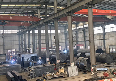 Our FactoryWe have a team of over 30 talented mobile fuel station R&D experts, as well as a 50,000-square-meter advanced modern intelligent manufacturing plant.
 - Mobile Fuel Station
- Storage Tank
- Blog
- Contacts


- Description
Containerized mobile refueling equipment (often called containerized skid-mounted fuel stations) is an integrated refueling system that utilizes international standard container dimensions (mainly 20 feet/40 feet), allowing for complete transport and rapid deployment. Its outer shell directly adopts the structure of a shipping container, offering greater transport versatility (suitable for global shipping) and higher container strength. The greatest value of this equipment lies in its safety, flexibility, and economy. In particular, the application of explosion-proof technology fundamentally distinguishes it from ordinary oil storage containers, enabling it to safely provide services near refueling points.


1. Design Principles
1.1 Design Objectives
To address the challenges of long construction cycles, limited site selection, and difficult relocation of traditional fixed gas stations, as well as the fuel replenishment needs of temporary operation scenarios (such as mines, construction sites, logistics parks, and emergency rescue sites), this design presents a mobile refueling equipment based on a standard container carrier. Through modular disassembly and integration, the equipment achieves rapid deployment, flexible combination, convenient relocation, and subsequent maintenance and upgrades, reducing construction and operating costs while meeting safety, environmental protection, and compliance requirements. It adapts to the replenishment needs of multiple scenarios and various oil products, filling the gaps in fuel supply in temporary and remote areas.
1.2 Design Principles
- Standardization Principle: Core modules adopt industry-standard and standard container sizes (e.g., 20ft, 40ft standard containers), with unified interfaces and specifications to ensure module interchangeability and compatibility, reducing production and maintenance costs. They are also compatible with various transportation modes such as road, rail, and sea, enabling cross-scenario transfer without additional modifications.
- Modularization Principle: Independent modules are broken down by function. Each module can be produced, tested, and transported independently, allowing for rapid on-site assembly and combination, and expansion as needed. This accommodates both single-product and mixed-product (gasoline, diesel, etc.) replenishment needs, adapting to different operational scales.
- Safety Principle: Fully complying with petrochemical safety regulations, the module design incorporates multiple protections including explosion-proof, fire-proof, leak-proof, anti-static, and lightning protection. Core components use explosion-proof materials, and critical systems are equipped with emergency shut-off functions to eliminate safety hazards and ensure safe operation of the equipment in complex environments such as field sites and temporary locations.
- Mobility Principle: Utilizing standard shipping containers as the carrier, the overall structure features a lightweight design (while still meeting strength requirements). Pre-installed lifting and forklift interfaces at the bottom allow for rapid relocation via trailers and forklifts, eliminating the need for complex disassembly. This ensures high deployment and evacuation efficiency and adapts to the dynamic needs of temporary operation scenarios.
- Environmental Principle: Equipped with oil recovery, leak collection, and oil and gas recovery systems to reduce oil loss and environmental pollution; the use of environmentally friendly materials and energy-saving components reduces energy consumption during operation, aligning with green development requirements.
- Maintainability Principle: Each module is structurally independent and easy to assemble and disassemble. Pre-installed inspection and maintenance interfaces allow for quick module replacement in case of failure, minimizing downtime; core components utilize mature and readily available standardized products, reducing maintenance costs and complexity.
1.3 Applicable Scenarios
The containerized mobile refueling equipment designed in this solution is suitable for the following scenarios: temporary work sites such as mining, construction, and field exploration; fixed temporary supply points such as logistics parks, ports, and bus stations; emergency fuel supply scenarios such as emergency rescue and disaster sites; remote areas, rural towns, and other areas lacking fixed refueling stations; and short-term concentrated fuel demand scenarios such as large-scale events and temporary markets.
2. Overall Structure and Module Division
The equipment uses a standard shipping container (preferably a 20ft high-cube container, expandable to 40ft containers as needed) as the carrier, adopting a "carrier module + functional module" splitting model. The overall design is sealed, ensuring waterproof, dustproof, and corrosion-resistant performance. Each functional module connects to the carrier module through standardized interfaces, allowing for flexible combination according to actual needs, achieving "one container for multiple uses, configured as needed."
The core modules are divided as follows: carrier module, oil storage module, refueling module, control system module, safety protection module, and auxiliary module. Each module is independently formed but works collaboratively to constitute a complete mobile refueling system. The module division follows the principles of "independent function, unified interface, and easy disassembly and assembly," ensuring that different modules can be freely combined, upgraded, and replaced, while reducing the difficulty of system integration.
3. Detailed Design of Each Module
3.1 Carrier Module (Core Carrier Unit)
3.1.1 Structural Design
The standard 20ft/40ft container is used as the basic carrier, made of Q235B carbon steel with wall thickness conforming to container industry standards. The surface undergoes sandblasting for rust removal and anti-corrosion coating treatment (epoxy zinc-rich primer + polyurethane topcoat), making it suitable for complex environments such as outdoor, humid, and dusty conditions, extending the equipment's service life. The container interior is leak-proof, with anti-corrosion lining at the bottom to prevent oil leakage from corroding the carrier structure. Ventilation and maintenance openings are provided at the top, and refueling windows and emergency exits are located on the sides, resulting in a rational layout that balances operational convenience and safety.
The container's bottom is welded with standardized lifting lugs and forklift slots, compatible with trailers, forklifts, cranes, and other transportation and lifting equipment, ensuring rapid transfer and lifting without additional modifications. The container door locks feature an explosion-proof sealing design to prevent external debris from entering and enhance anti-theft performance. Furthermore, the container's interior has pre-installed modular installation interfaces (mechanical, electrical, and piping interfaces) of uniform size and specifications, ensuring quick and easy installation of all functional modules.
3.1.2 Auxiliary Design
Adjustable outriggers are installed at the bottom of the container for horizontal fixation after equipment deployment, adapting to different terrains (e.g., slopes <=5o) to ensure stable equipment operation. Safety warning signs (e.g., "No Smoking," "Flammable and Explosive," "Anti-static") are affixed to the sides, complying with petrochemical safety regulations. The interior is equipped with emergency lighting and escape route markings to enhance emergency response capabilities. Additionally, the container can be fitted with an insulation layer as needed to adapt to low-temperature environments (-20oC-50oC) to prevent oil solidification or damage to equipment components.
3.2 Oil Storage Module (Oil Storage Unit)
3.2.1 Structural Design
As the core functional module, the oil storage module adopts a double-layer explosion-proof tank design. The inner layer is made of corrosion-resistant, high-strength stainless steel (304 or 316L), and the outer layer is a carbon steel protective layer. The middle layer is filled with heat-insulating and explosion-proof materials (such as fiberglass or explosion-proof aluminum alloy honeycomb materials). This design not only prevents oil corrosion of the tank but also provides explosion protection and insulation. It can withstand a 12-joule gunshot test without explosion, far exceeding industry safety standards. The tank volume can be designed according to requirements (e.g., 5m³, 10m³, 20m³), adapting to 20ft/40ft container dimensions, ensuring the tank can be installed as a whole into the carrier module without disassembly.
The tank is equipped with baffles to reduce oil sloshing during equipment movement and lower the risk of center of gravity shift. A breather valve, safety valve, and level gauge interface are located at the top; an oil outlet and drain outlet are located at the bottom; and an inspection port is located on the side for easy oil filling, drainage, and tank maintenance. To meet diverse oil refueling needs, multi-compartment storage tanks (such as dual-compartment or triple-compartment tanks) can be designed. Each compartment is independently sealed and can store different oil products such as gasoline and diesel, achieving a "one-machine-multiple-oil" function to adapt to diverse refueling requirements.
3.2.2 Leakage Prevention and Environmental Protection Design
The storage tank adopts a double-layer sealing structure, with a leak detection sensor installed between the inner and outer layers. In the event of an oil leak, it can monitor in real time and issue an alarm signal. Simultaneously, the leaked oil is collected through a leak collection tank to prevent soil and water pollution. The top of the storage tank is equipped with an oil vapor recovery interface, which can be connected to an oil vapor recovery device to recover and reuse the oil vapors volatilized from the oil, reducing oil loss and air pollution. The oil vapor recovery rate can reach over 95%, meeting environmental protection standards. Furthermore, the storage tank is wrapped with an external insulation layer, which can effectively control the oil temperature, reduce volatilization loss, and adapt to high-temperature and low-temperature environments.
3.3 Refueling Module (Fuel Output Unit)
3.3.1 Core Component Design
The refueling module consists of an explosion-proof refueling machine, fuel pipeline, refueling nozzle, filter, and other components. All components are explosion-proof, complying with GB3836 series explosion-proof standards and suitable for flammable and explosive environments. The explosion-proof refueling machine is a miniaturized, integrated model that can be embedded in the refueling window on the side of a container. It is easy to operate and supports both quantitative and fixed-amount refueling modes. It is equipped with an LCD screen that displays parameters such as refueling volume, amount, and oil temperature in real time, facilitating recording and management by operators.
The fuel pipeline uses corrosion-resistant and high-pressure-resistant stainless steel pipes. Pipeline connections use explosion-proof sealed joints to prevent fuel leakage. A precision filter is installed in the pipeline to filter impurities in the fuel, protecting the refueling machine and engine, and extending the equipment's service life. The refueling nozzle is an explosion-proof self-sealing nozzle that automatically shuts off after refueling to prevent dripping. It is also equipped with an anti-static hose to eliminate static electricity hazards. Depending on operational needs, 1-2 refueling nozzles can be configured, with a single nozzle refueling flow rate of 40L/min-80L/min, adaptable to the refueling needs of different vehicle types (small vehicles, large engineering vehicles). Quick connectors can also be configured to meet the refueling needs of special equipment such as drones.
3.3.2 Pipeline Layout Design
The oil pipeline adopts a concealed layout, laid on both sides inside the container, avoiding maintenance passages and electrical components, reducing pipeline wear and collision risks. Maintenance interfaces are reserved in the pipeline for easy future maintenance and replacement. Valves are installed at key locations in the oil pipeline (such as the storage tank outlet and the refueling machine inlet), allowing for manual or automatic control of pipeline on/off. In emergencies, the oil supply can be quickly cut off to prevent oil leakage and spread. Simultaneously, the pipeline design follows the "horizontal inlet and outlet" principle, reducing bends and resistance, and improving refueling efficiency.
3.4 Control System Module (Intelligent Control Unit)
3.4.1 Hardware Design
The control system module uses a PLC (Programmable Logic Controller) as the core control unit, paired with a touch screen operation panel, to achieve automated control and parameter monitoring of the equipment. The core hardware includes: a PLC controller, touchscreen, level sensor, pressure sensor, temperature sensor, leak detection sensor, explosion-proof camera, and emergency shut-off button. All electrical components are explosion-proof to ensure safe operation in flammable and explosive environments.
The level sensor is installed inside the oil storage tank to monitor the oil level in real time. When the level is below the warning value or above the upper limit, it automatically issues an alarm signal and stops the refueling machine. The pressure sensor monitors the pressure of the oil pipeline to prevent overpressure leaks. The temperature sensor monitors the temperature of the oil in the tank and issues an alarm when the temperature is abnormal (e.g., excessively rapid evaporation of oil in high-temperature environments). The leak detection sensor works with the double-layer structure of the tank to monitor oil leaks in real time and respond quickly. Furthermore, the control system can be configured with a 4G/5G module interface for remote monitoring. Operators can view equipment operating parameters, level, and alarm information in real time via a mobile app or computer, and remotely control the equipment to start and stop, reducing manual monitoring costs.
3.4.2 Software Design
The control system software adopts a modular design, divided into five major functional modules: parameter monitoring, control execution, alarm, data statistics, and remote communication. The user interface is simple and intuitive, allowing operators to quickly learn how to use it. The parameter monitoring module collects data such as liquid level, pressure, temperature, and leakage in real time, displaying it synchronously on the touchscreen. The control execution module can realize operations such as starting and stopping the fuel dispenser, opening and closing the fuel valve, and emergency shut-off, supporting both automatic and manual control modes. The alarm module issues audible and visual alarms for abnormal liquid level, abnormal pressure, leakage, and power failure, and records alarm information for easy traceability. The data statistics module automatically records data such as fuel dispensing volume, number of dispensing operations, and fuel consumption, generating statistical reports and supporting data export for convenient operation and management. The remote communication module enables real-time linkage between the equipment and the monitoring center, supporting remote control, parameter setting, and fault diagnosis, improving equipment operation and maintenance efficiency.
3.5 Safety Protection Module (Safety Assurance Unit)
The safety protection module is the core guarantee for the safe operation of the equipment, covering multiple aspects such as explosion-proof, fire-proof, anti-static, lightning protection, and emergency response. It fully complies with petrochemical safety regulations, ensuring the safety and reliability of the equipment in various scenarios.
- Explosion-proof protection: All electrical components (controllers, fuel dispensers, sensors, cameras, etc.) adopt explosion-proof design, with an enclosure protection rating of IP65, preventing electrical sparks from igniting oil and gas; storage tanks, oil pipelines, fuel nozzles, and other components are all made of explosion-proof materials to avoid sparks generated by collisions; explosion-proof ventilation fans are installed inside the container to maintain internal air circulation, reduce oil and gas concentration, and prevent oil and gas accumulation from causing an explosion.
- Fire protection: The container is equipped with dry powder fire extinguishers and carbon dioxide fire extinguishers (the number is configured according to the storage tank volume), placed in easily accessible locations; fireproof baffles are installed at the refueling windows to prevent external ignition sources from entering; flammable and explosive materials are prohibited from being piled up around the equipment, and fire prevention warning signs are affixed; at the same time, the safe distance between the equipment and fire and heat sources is not less than 10m, complying with safety regulations.
- Anti-static protection: The container is equipped with an anti-static grounding device at the bottom, with a grounding resistance of no more than 4Ω, to promptly conduct static electricity generated during equipment operation to the ground. Refueling nozzles and oil hoses are also equipped with anti-static devices, and operators wear anti-static work clothes and shoes to prevent static electricity accumulation and potential safety hazards.
- Lightning protection: A lightning rod is installed on the top of the container, higher than the highest point of the equipment. The grounding device is shared with the anti-static grounding device to ensure rapid conduction of lightning current to the ground, preventing damage to equipment or fire/explosion caused by lightning strikes. The electrical system is equipped with surge protectors to protect control modules and electrical components from lightning strikes.
- Emergency response: The equipment is equipped with an emergency shut-off button (manual + automatic). In emergencies (such as leaks or fires), the oil pipeline and power supply can be quickly cut off to stop equipment operation. An emergency exit is located on the side of the container for easy evacuation of operators. An emergency leak handling kit (absorbent cotton, oil booms, etc.) is provided to quickly handle small oil leaks and prevent the spread of pollution. The control system has a built-in emergency response procedure that automatically prompts operators to take action after an alarm, minimizing accident losses.
3.6 Auxiliary Modules (Supporting Support Units)
Auxiliary modules are configured according to actual application needs and mainly include a power supply module, oil and gas recovery module, maintenance module, and insulation module. These provide supporting support for the normal operation of the equipment, improving its applicability and convenience.
- Power Supply Module: Adopts a dual power supply mode of "mains power + backup generator," with mains power supply as the priority, suitable for scenarios with mains power access. In scenarios without mains power, the backup generator (power configured according to the total power consumption of the equipment, such as 10kW or 15kW) is activated to ensure continuous operation. The generator adopts an explosion-proof design, is placed in an independent compartment of the container, and is equipped with a silencer to reduce operating noise (controlled below 55 decibels), suitable for noise-sensitive scenarios such as urban areas and residential areas. Simultaneously, a photovoltaic charging module can be configured to achieve green and energy-saving power supply, suitable for remote scenarios without mains power. The photovoltaic modules can be cascaded to expand and meet the power supply needs of the equipment.
- Oil and Gas Recovery Module: Linked with oil storage tanks and refueling machines, this module recovers oil and gas volatilized during refueling back to the storage tank or a dedicated recovery unit, reducing oil loss and air pollution, meeting environmental protection requirements. The module features a compact design and can be directly integrated into the container, requiring no additional space. It boasts high oil and gas recovery efficiency and is easy to maintain.
- Maintenance Module: The container has a pre-reserved maintenance passage (at least 0.8m wide), equipped with a tool storage cabinet and emergency lighting, facilitating daily maintenance and repair. Each module has pre-reserved maintenance interfaces for quick disassembly and replacement of components, minimizing downtime. It also includes an oil sampling interface for periodic oil quality testing.
- Insulation Module: For low-temperature environments (such as northern winters), an insulation layer (using polyurethane insulation material) is added to the container and storage tank to prevent oil solidification and freezing damage to equipment components. A heating device (explosion-proof electric heating) can be configured to heat the oil in the storage tank at low temperatures, ensuring normal equipment operation. In high-temperature environments, a heat dissipation device can be configured to reduce the internal temperature of the equipment, protecting electrical components and oil.


4. Module Integration and Installation & Commissioning
4.1 Module Integration Process
This equipment adopts an integration model of "factory prefabrication + on-site assembly," significantly shortening on-site deployment time and ensuring controllable equipment quality. The specific process is as follows:
- 1. Factory Prefabrication: Each functional module (oil storage module, refueling module, control system module, etc.) is independently produced and tested in the factory to ensure that each module meets performance standards and interface compatibility; the carrier module completes anti-corrosion, sealing, and interface pre-reservation processing, completing preliminary preparations.
- 2. Module Pre-installation: In the factory, core modules such as the oil storage module, control system module, and safety protection module are pre-installed onto the carrier module, connecting pipelines and electrical lines, and conducting preliminary commissioning to ensure that each module works normally in tandem.
- 3. Transportation and Deployment: The pre-installed equipment is transported to the work site by trailer, ship, or other means; the equipment is hoisted to the designated position using cranes and forklifts, the outriggers are adjusted, and the equipment is secured to ensure that it is level and stable.
- 4. On-site Assembly: Assemble the refueling module and auxiliary modules (such as the oil and gas recovery module and backup generator) on-site according to actual needs, connect pipelines and electrical interfaces to complete module integration; conduct a comprehensive inspection of the equipment to ensure good interface sealing and correct wiring connections.
4.2 Installation and Commissioning Requirements
- Before installation, conduct a site survey to ensure the site is flat, firm, and far away from fire sources, heat sources, and residential areas, meeting safety distance requirements; check the site's power supply and grounding conditions to ensure they meet the equipment's operational requirements.
- During installation, strictly follow the design drawings to ensure precise interface connections and good sealing of all modules, no leaks in the oil pipelines, standardized electrical wiring connections, and reliable grounding; after installation, thoroughly clean the equipment to remove debris and oil stains.
- Commissioning is divided into no-load commissioning and load commissioning: No-load commissioning mainly tests the operation of the control system, safety protection system, and power supply system to ensure that each module functions normally and alarms are accurate; load commissioning tests the operation of the refueling module and oil storage module by adding oil, checking functions such as refueling flow rate, liquid level monitoring, and oil and gas recovery to ensure the equipment meets actual operational needs.
- After commissioning, compile the commissioning records and train the operators to ensure they are familiar with the equipment operation procedures, safety precautions, and emergency response methods before putting it into use.
5. Relocation and Maintenance Plan
5.1 Equipment Relocation
This equipment has rapid relocation capabilities. The relocation process does not require disassembling the core modules. The specific process is as follows:
- 1. Pre-relocation preparation: Stop the equipment operation, disconnect the power supply and oil pipelines, and close all valves; transfer the remaining oil in the storage tank to a dedicated container (if necessary), and clean the internal debris and oil stains of the equipment; check the hoisting and transportation equipment to ensure it is in good working order.
- 2. Equipment hoisting: Use a crane to hoist the entire equipment onto the trailer and secure it firmly, ensuring that the equipment does not shake or shift during transportation; check the container door locks and outriggers to ensure they are closed and retracted properly.
- 3. Transportation and transfer: Transport the equipment to the new work site by trailer. During transportation, strictly adhere to traffic rules and avoid severe bumps and collisions to ensure equipment safety; for long-distance transportation, shipping, rail, and other transportation methods can be used to adapt to different transfer needs.
- 4. Redeployment: Hoist the equipment to the new site, adjust and secure the outriggers, connect the power supply and pipelines, perform simple debugging, and once the equipment is confirmed to be operating normally, it can be put back into use. A single relocation can be controlled within 4 hours, significantly improving operational flexibility.
5.2 Daily Maintenance and Upkeep
To extend the equipment's service life and ensure its safe and stable operation, the following daily maintenance and upkeep plan is established, following the principles of "regular inspection, timely maintenance, and prevention first":
- Daily Maintenance: Inspect the equipment's exterior for damage or leaks; inspect the refueling nozzle and oil pipelines for drips or damage; inspect the control system to check if parameters such as liquid level, pressure, and temperature are normal; check fire extinguishers and emergency equipment to ensure they are in good working order; clean debris and oil stains around the equipment to maintain a clean working environment.
- Weekly Maintenance: Check the drain outlet of the oil storage tank to drain accumulated water and impurities; check the filter and clean impurities from the filter element; check the grounding device to ensure reliable grounding; check the ventilation fan to ensure normal operation; calibrate the control system to ensure accurate parameter monitoring.
- Monthly Maintenance: Check the tank's seal for leaks; check electrical wiring for aging or damage; check the backup generator and conduct a no-load test run to ensure normal emergency power supply; check the oil and gas recovery module, clean the recovery pipelines, and ensure recovery efficiency; lubricate and maintain all equipment components.
- Annual Maintenance: Conduct a comprehensive inspection of the oil storage tank (e.g., hydrostatic test, leak detection) to ensure good tank performance; replace aging pipelines, seals, filters, etc.; conduct a comprehensive overhaul of the control system and upgrade the software version; perform comprehensive rust removal and anti-corrosion treatment on the equipment to extend its service life; commission a professional organization to conduct a safety inspection of the equipment to ensure compliance with requirements.
5.3 Fault Handling
If a fault occurs during equipment operation, the operator should immediately stop the equipment, disconnect the power supply and oil pipelines, and take emergency measures to prevent the fault from escalating; at the same time, based on the fault symptoms, investigate the cause of the fault and handle it promptly. The specific fault handling procedure is as follows:
- 1. Alarm Response: When the equipment issues an audible and visual alarm (e.g., abnormal liquid level, leakage, abnormal pressure), the operator should immediately check the alarm information displayed on the control system to determine the fault type.
- 2. Emergency Response: In case of oil leakage, immediately activate the emergency shut-off button to stop oil supply. Use absorbent cotton, oil booms, and other tools to handle the leaked oil and prevent the spread of pollution. In case of fire, immediately use fire extinguishers to extinguish the fire, organize personnel evacuation, and call emergency numbers.
- 3. Troubleshooting: Based on the alarm information and fault symptoms, investigate the cause of the fault (e.g., pipeline leak, sensor failure, electrical fault, etc.). For simple faults (e.g., clogged filter element, loose wiring), operators can handle them on-site. For complex faults (e.g., tank damage, control system failure), immediately contact professional maintenance personnel, stop equipment operation, and await repair.
- 4. Fault Recovery: After the fault is resolved, conduct a comprehensive inspection and debugging of the equipment. Only after confirming that the equipment is operating normally can it be put back into use. Simultaneously, record the fault handling process for future traceability and improvement.
6. Solution Advantages and Innovations
6.1 Solution Advantages
- High Flexibility: Adopting a modular design, modules can be flexibly combined according to needs, adapting to single-fuel and multi-fuel replenishment requirements; the equipment can be quickly migrated and deployed without complex civil engineering, adapting to various scenarios such as temporary, remote, and emergency situations, reducing migration costs by more than 70% compared to traditional gas stations.
- High Safety: Incorporating multiple protection designs including explosion-proof, fire-proof, leak-proof, anti-static, and lightning strike protection; core components use explosion-proof materials; the control system monitors the equipment's operating status in real time; and it has comprehensive emergency response capabilities, effectively eliminating safety hazards and meeting the requirements for operation in flammable and explosive environments.
- Controllable Costs: Using standardized modules and standard containers, production, transportation, and installation costs are lower; the modular design facilitates later maintenance and upgrades; modules can be added or replaced as needed without replacing the entire equipment, reducing operating and maintenance costs; the factory prefabrication mode significantly shortens deployment time and reduces on-site construction costs.
- Environmental Compliance: Equipped with oil and gas recovery and leak collection systems, reducing oil loss and environmental pollution, meeting national environmental protection requirements; using environmentally friendly materials and energy-saving components reduces energy consumption and achieves green operation.
- High Level of Intelligence: Utilizes a PLC control system to achieve automated equipment operation and real-time parameter monitoring, supporting remote monitoring and operation, reducing manual on-site costs and improving maintenance efficiency; data statistics functions facilitate operation management and achieve refined operation.
6.2 Innovation Points
- Modular Integration Innovation: Oil storage, refueling, control, and safety protection functions are separated into independent modules with standardized interfaces, enabling "on-demand combination and expansion" to adapt to different operation scales and scenarios, while facilitating module upgrades and replacements, extending equipment lifespan.
- Dual Protection and Intelligent Monitoring Innovation: The storage tank adopts a double-layer explosion-proof structure, coupled with leak detection sensors, to achieve real-time monitoring and rapid handling of oil leaks; the control system integrates multi-dimensional sensors to achieve comprehensive monitoring of equipment operating parameters and links with emergency shut-off functions, improving safety assurance levels.
- Mobility Optimization Innovation: Utilizing standard containers as the carrier, optimized hoisting and fixing designs enable rapid equipment migration and deployment without disassembling core modules, resulting in high migration efficiency. It adapts to various transportation methods, expanding the equipment's application range, especially suitable for dynamic operation scenarios such as mines and emergency rescue.
- Multi-Scenario Adaptability Innovation: Through flexible configuration of auxiliary modules, it supports multiple power supply modes such as mains power, backup generators, and photovoltaics, adapting to different environments including no mains power, low temperatures, and high temperatures. The multi-compartment storage tank design allows for simultaneous replenishment of multiple fuel types, meeting diverse operational needs.


7. Conclusion
This modular design scheme for containerized mobile refueling equipment, using standard containers as the carrier, achieves rapid deployment, flexible migration, safe operation, and convenient maintenance through functional modular disassembly and integration. It effectively solves the limitations of traditional fixed refueling stations and adapts to various fuel replenishment scenarios such as temporary, remote, and emergency refueling. The solution strictly adheres to safety, environmental protection, and compliance requirements, balancing practicality and innovation, and can meet the fuel replenishment needs of mines, construction sites, logistics parks, emergency rescue, and other fields, demonstrating broad application prospects.
Based on feedback from actual applications, the module design can be further optimized to improve the equipment's intelligence, energy efficiency, and adaptability to various scenarios, thereby promoting the standardization and large-scale development of mobile refueling equipment and providing a more efficient, safe, and environmentally friendly solution for temporary and remote energy replenishment.


Leading Chinese Manufacturer & Exporter of mobile fuel stations and skid-mounted fuel stations.