- Home
- Company
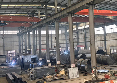 Our FactoryWe have a team of over 30 talented mobile fuel station R&D experts, as well as a 50,000-square-meter advanced modern intelligent manufacturing plant.
 - Mobile Fuel Station
- Storage Tank
- Blog
- Contacts


8 Key Measures for Corrosion Prevention of Mobile Fuel Station Tanks
mobile fuel stations, as the core carrier of skid-mounted refueling units, are widely used in logistics parks, industrial and mining enterprises, and temporary fuel supply scenarios due to their mobility, flexibility, and rapid deployment. However, unlike fixed gas stations, mobile fuel station tanks are constantly subjected to dynamic conditions such as transportation bumps, loading and unloading impacts, and complex outdoor environments, facing the combined challenges of vibration loads, media erosion, electrochemical corrosion, and alternating stress. Once a tank corrodes and leaks, it will not only cause fuel loss and environmental pollution but may also lead to serious safety accidents such as fires and explosions. Therefore, constructing a systematic, robust, and mobile-adaptive tank corrosion prevention system is crucial to ensuring the safe operation of mobile fuel stations throughout their entire lifecycle. The following summarizes eight key measures for corrosion prevention of mobile fuel station tanks from the dimensions of material selection, coating protection, cathodic protection, structural design, and inspection and maintenance.


1. Select Corrosion-Resistant Tank Materials
Address the problem at its source. It is recommended to use austenitic stainless steel (such as 304 or 316L) as the tank material. If carbon steel (such as Q235-B) is used, a coating protection is necessary, and the wall thickness should allow for sufficient corrosion tolerance (usually not less than 6mm) to withstand mechanical damage and electrochemical corrosion.
1.1. Stainless Steel Double-Layer Tank
Stainless steel is ideal for harsh corrosive environments, especially recommended for mobile or frequently relocated mobile fuel stations.
- Inner Tank: 316L stainless steel: Contains molybdenum, exhibiting extremely strong resistance to chloride ion corrosion (such as coastal salt spray) and crevice corrosion. It also possesses excellent low-temperature impact toughness, maintaining high toughness even at -50oC, making it ideal for cold northern regions or coastal areas with high salt spray.
- Outer Tank: 304 stainless steel: Serves as an outer protective layer, providing good overall corrosion resistance and strength, forming a "double insurance" with the inner tank.
- Structural Advantages: The double-layer tank design (the distance between the inner and outer tank walls is typically 100-150mm) allows for the integration of fiber optic sensors or pressure monitoring systems in the interlayer, enabling real-time alarms for even minor leaks.
- Corrosion Protection: Stainless steel itself achieves corrosion resistance through alloying, eliminating the need for additional coatings and fundamentally solving the problem of coating aging and peeling.
1.2. SF Double-Wall Tanks:
SF (steel-fiberglass) double-wall tanks are currently the most widely used solution in mobile fuel stations and underground tank markets, offering good economic benefits while ensuring safety and environmental protection.
- Inner Tank (Steel): Typically made of Q235-B carbon steel, with a thickness of not less than 6mm, providing sufficient pressure resistance and structural rigidity. To extend service life, a corrosion allowance is provided (tank wall >=1mm, tank bottom >=2mm), and the interior is coated with conductive heavy-duty anti-corrosion coatings such as epoxy phenolic resin or titanium nanofiber.
- Outer Tank (FRP Fiberglass): >=2.5mm thick, constructed of glass fiber reinforced plastic, it is the main force in corrosion protection. It is completely free from electrolytic corrosion by groundwater, salt water, or oil, and its chemical properties are extremely stable.
- Gap Layer: A 1-3.5mm through space is reserved between the inner and outer tanks to accommodate a 24-hour leak detector. If the inner tank leaks, oil will accumulate in this gap, triggering an alarm and preventing further contamination.
- Supplementary Protection: For carbon steel inner tanks, in addition to the coating, sacrificial anode cathodic protection (such as zinc blocks) is usually applied to further inhibit electrochemical corrosion.
1.3. Key Considerations for Material Selection
The medium and environment determine the direction: SF6 tanks offer high cost-effectiveness for storing conventional oils such as gasoline and diesel in environments with low corrosiveness. For storing highly corrosive oils such as alcohol-containing gasoline and biodiesel, or in locations near the sea or chemical plants, 316L stainless steel should be prioritized.
- Consider the total life cycle cost: Although stainless steel tanks have a higher initial investment, their long maintenance-free period makes them particularly suitable for skid-mounted applications where frequent maintenance is difficult. SF6 tanks have a moderate initial investment, but require regular inspection of the coating and anode blocks.
- Strict adherence to compliance: Regardless of the material chosen, the product must comply with GB50156-2021 "Technical Standards for Automobile Fueling, Gasoline Refueling, and Hydrogen Refueling Stations" and relevant industry regulations.
2. High-standard internal anti-corrosion coating
Due to the frequent shaking of mobile tanks, the coating is highly susceptible to erosion and corrosion from fuels (especially alcohol-containing gasoline and biodiesel).
2.1. Coating System and Dry Film Thickness (Core)
2.1.1. Standard System (Three-Layer/Four-Layer)
- Three-Layer System: Epoxy Zinc-Rich Primer + Epoxy Mica/Glass Flake Intermediate Coat + Oil-Resistant Conductive Epoxy Topcoat.
- Four-Layer System: Epoxy Zinc-Rich Primer + Epoxy Mica + Epoxy Glass Flakes + Conductive Epoxy Topcoat.
2.1.2. Dry Film Thickness (DFT) of Each Layer
| Coating | Dry Film Thickness | Key Requirements |
| Epoxy Zinc-Rich Primer | 80–100µm | Zinc content >=80%, Rust-proof and Conductive |
| Epoxy Mica Intermediate Coat | 100–120µm | Shielding, Thickening |
| Epoxy Glass Flakes (Optional) | 120–150µm | Impermeable, Media-resistant |
| Conductive epoxy topcoat | 80–100µm | Surface resistivity 106–109ohm, oil resistant |
| Total dry film thickness | >=320µm (three layers); >=400µm (four layers) | Meets C5-M heavy-duty anti-corrosion requirements |
2.1.3. Thickness Acceptance Rules
- Follow the 90-10 principle: 90% of measuring points >= design value, the rest >=90% of design value.
- >=5 points per 10m2, double the number of points for welds/corners/oil-gas interfaces.
- Allowable deviation: -25µm, single point not less than 85% of design value.
2.2. Surface Treatment (Anti-corrosion base)
- Rust removal grade: Sa2.5 (very thorough sandblasting), no visible oil, scale, or weld slag.
- Surface roughness: 40–75µm (shot blasting) / 60–100µm (angular material).
- Substrate Temperature: >=3oC above dew point to avoid condensation.
- Weld Treatment: Grind to a radius of >=2mm, without sharp edges.
2.3. Adhesion (Core Mechanical Indicator)
- Cross-cut Test: Grade 0–1, no large-scale peeling.
- Pull-off Test: >=8MPa (solvent-free epoxy).
- Sampling Ratio: >=1% area, >=3 points per can.
2.4. Electrostatic Discharge Performance (Mandatory Safety)
- Topcoat Surface Resistivity: 106–109ohm .
- Testing: Surface resistivity tester, >=1 point per 20m2.
2.5. Resistance to Media and Aging
- Resistance to Gasoline/Diesel Immersion: No blistering, peeling, or discoloration after 72h.
- Salt Spray Resistance: >=1000h (neutral salt spray).
- Resistance to damp heat: >=500h.
- Impact resistance: >=50kg*cm.
2.6. Construction environment and process
- Temperature: 5–35oC; Humidity: <=85%; Wind speed: <=5m/s.
- Two-component: Mix according to ratio, mature for 15–30min, pot life 4–8h.
- Coating interval: Primer >=8h, intermediate coat >=12h, topcoat >=24h (room temperature).
- No missed coating, runs, pinholes, bubbles, or cracks
2.7. Spark leak detection (integrity)
- Detection voltage: 5V/µm (total thickness 320µm->1600V; 400µm->2000V).
- Detection range: Full inner wall, no pinholes or leaks.
- Defects found: Sand down to the substrate, recoat according to the system and re-inspect.
2.8. Acceptance and Maintenance Cycle
- Acceptance Items: Thickness, Adhesion, Electrical Spark, Static Electricity Dissipation, Appearance, Media Resistance.
- Warranty: >=10 years (High-standard design).
- Maintenance: Inspect coating integrity every 6–12 months; repair any damage immediately.
3. Heavy-duty Anti-corrosion Coating and Weather-resistant Design for External Wall
The outer wall of the mobile tank is exposed to sunlight, rain, wind and sand impact, and salt spray (coastal transportation) for extended periods.
3.1. Core Design Basis
The design and acceptance of skid-mounted gas stations are primarily based on the following two standards, which have specific requirements for coating corrosion protection:
- SH/T 3134-2023 "Technical Standard for Skid-Mounted Automobile fuel stations": This is a dedicated technical standard for skid-mounted equipment, specifying the construction and protection requirements for the main body of the tank (outer tank).
- SH/T 3022-2019 "Design Standard for Corrosion Protection Coatings for Petrochemical Equipment and Pipelines": Specifies the coating system, minimum total dry film thickness, and surface treatment grade.
3.2. Coating System and Thickness Design
Depending on the corrosive environment faced by different parts of the skid-mounted equipment, the coating design should be treated differently for each area. Based on the recommendations in Appendices C and D of SH/T 3022-2019, and considering the characteristics of skid-mounted equipment, the following data is recommended:
| Structural Part | Recommended Coating System | Recommended Number of Coats | Minimum Total Dry Film Thickness (µm) | Design Specifications |
| Outer Tank Body (Steel) | Epoxy Zinc-Rich Primer + Epoxy Mica Iron Oxide Intermediate Coat + Acrylic Polyurethane Topcoat | 3-4 Coats | >= 240 | Corrosion resistance grade C5 or higher, withstands sun and rain exposure, topcoat must be UV resistant |
| Steel Structure Skid | Epoxy Zinc-Rich Primer + Epoxy Mica Iron Oxide Intermediate Coat + Acrylic Polyurethane/Fluorocarbon Topcoat | 3 Coats | >= 200 | Withstands mechanical vibration, requires good adhesion |
| Explosion-Proof Wall/Dike | Thick-film Epoxy Coating (Or epoxy coal tar pitch) | 2-3 coats | >= 300 | For long-term contact with oil and water stains, chemical penetration resistance is required. |
Note: For equipment in areas with strong ultraviolet radiation or with high requirements for color and gloss retention, the topcoat can be upgraded to a fluorocarbon topcoat (dry film thickness >= 70µm), with a design life of 15-20 years.
3.3. Key Performance Indicators
In addition to meeting the thickness requirements, the coating must meet the following physical and chemical performance indicators (refer to HG/T 4569-2013 and SH/T 3022 requirements):
- Salt spray resistance: >= 1000 hours, unidirectional corrosion at the etched line <= 2mm (this is a key indicator for evaluating heavy-duty corrosion resistance).
- Aging resistance: Artificial accelerated aging >= 1000 hours, no blistering, no chalking, no cracking (requirements for acrylic polyurethane topcoats).
- Oil Resistance: Resistant to 120% solvent oil or 93% gasoline for >= 720 hours without any abnormalities in the paint film (to accommodate potential oil splashes).
- Static Electricity Dissipation: Surface resistivity should be between 105 and 1011 ohm.
- Adhesion: Pull-off test >= 5 MPa, or cross-cut test <= Grade 1.
3.4. Substrate Preparation and Application Requirements
Even the best coatings rely on high-quality substrate preparation. The design data must include the following key application parameters:
- Surface Treatment Grade: Steel surfaces must be sandblasted or shot-blasted to achieve a grade of Sa2.5 (i.e., near-white, with no visible grease, dirt, scale, rust, or paint coating; residual traces are only slight spots or streaks).
- Surface Roughness: After rust removal, the surface roughness should be controlled between 40 µm and 85 µm (usually corresponding to the Rz value) to ensure the mechanical adhesion of the primer.
- Environmental Restrictions: The ambient temperature for application should be >=5oC, and the relative humidity <= 85%. Application is strictly prohibited when the substrate surface temperature is below 3oC below the dew point.
3.5. Additional Requirements for Thermal Insulation and Sun Protection
The outer wall of the gasoline tank in a skid-mounted gas station not only needs corrosion protection but also must have thermal insulation. Standard SH/T 3134-2023, Clause 4.1.8, stipulates that the tank should be equipped with thermal insulation or sun protection measures, and the insulation material should be non-combustible.
- Design strategy: High weather resistance and high reflectivity white or light-colored topcoat are usually used as sun protection layer (solar reflectance >= 0.80), or a non-combustible heat insulation layer (such as aerogel felt, composite silicate board, etc.) is laminated between the intermediate coating and the topcoat to prevent the internal temperature of the oil tank from being too high and causing safety hazards.
4. Sacrificial Anode Cathodic Protection System
For steel tanks, electrochemical corrosion is highly likely to occur at points of coating damage. Since the mobile tanks are not fixed in position, a potentiostat with an applied current cannot be used; therefore, sacrificial anodes must be installed.
4.1. System Design General Requirements
- Protected Objects: Bottom of skid-mounted tank, lower part of outer wall, supports, buried pipelines.
- Protected Environment: Concrete foundation/asphalt sand cushion layer, soil, humid atmosphere.
- Protection Method: Sacrificial anode method (primarily magnesium anodes).
- Design Life: >=15 years (high-standard configuration for mobile fuel stations).
- Protection Potential Index: -0.85 V - -1.20 V; overprotection is strictly prohibited to prevent cathodic stripping of the coating.
4.2. Anode Material Selection and Key Parameters
4.2.1. Optimal Anode Material Selection
Fuyuan mobile fuel station standard high-configuration uses high-purity magnesium anodes (Mg-Mn-Ce system). Core performance data are as follows.
- Open circuit potential: <= -1.50 V (CSE).
- Operating potential: -1.40 V - -1.50 V (CSE).
- Current efficiency: >=50%.
- Theoretical capacitance: 181.03 A*h/g.
- Actual consumption rate: <=7.8 kg/(A*a).
4.2.2. Common anode specifications
- Specification: 11kg strip/block magnesium anode.
- Filler pack: Chemical filler, gypsum:bentonite:sodium sulfate = 75:20:5.
- Packing thickness: >=50mm.
- Packing bag diameter: >=200mm.
4.3. Arrangement Quantity and Installation Data
4.3.1. Arrangement Principles
- Evenly distributed around the tank bottom perimeter.
- Avoid areas of hoisting, support, and weld stress.
- Distance between anode and tank wall: 0.5-1.0m.
- Spacing between anodes: 3-5m.
4.3.2. Typical Configuration Quantity
Taking a common 20m3-50m3 skid-mounted tank as an example:
- Each skid-mounted tank: 4-6 11kg magnesium anodes.
- Total protective current: 0.2-0.5 A.
4.3.3. Cable and Connection Requirements
- Cable type: BVV 1*4mm2 or VV 1*6mm2 copper core cable.
- Anode steel core and cable: Exothermic welding + tin sealing.
- Insulation sealing: Double sealing with epoxy resin and heat shrink tubing.
- Cables are led to the test post/junction box for easy later testing.
4.4. Electrical Parameter Design
4.4.1. Protection Current Density
- Intact Coating Tank: 0.5-1.0 mA/m2.
- Locally Damaged Areas: 5-10 mA/m2.
4.4.2. Single Anode Output Current
- 11kg Magnesium Anode: =0.05-0.10 A/anode.
4.5. Test Post and Testing System Data
One test post is installed per skid-mounted tank.
- Test post configuration: Potential test terminal, anode/tank wiring terminal, reserved interface for Cu/CuSO4 reference electrode.
- Test post height: >=500mm.
- Clearly marked: Cathodic Protection Test Post.
4.6. Acceptance Testing Standards
- Power-Off Potential Test: Power-off potential must be between -0.85 V and -1.20 V.
- Polarization Potential Decay: A negative potential shift of >=100mV within 4 seconds after power failure indicates effective polarization.
- Insulation Inspection: Insulation resistance between the anode system and the tank body >=1 Mohm.
- Connection Resistance: Contact resistance at cable connection points <=0.01 ohm.


5. Prevention of Dissimilar Metal Contact Corrosion
When the mobile fuel station tank is installed on the vehicle chassis or trailer frame, direct welding or rigid bolt connection to the carbon steel chassis will create a "large cathode-small anode" corrosion cell.
- Insulating gaskets (such as rubber asbestos sheets or PTFE sheets) and insulating sleeves must be installed between the tank body and the support base and fastening straps.
- Ensure there is no direct metal conduction path between the tank body and the vehicle frame to prevent galvanic corrosion.
6. Strict Welding Process and Weld Treatment
The mobile tank body is subjected to continuous vibration and alternating loads; the weld seam is the weakest point for corrosion.
- Post-welding stress-relief heat treatment (if applicable) is mandatory to prevent stress corrosion cracking (SCC).
- All welds must be ground smooth and subjected to 100% non-destructive testing (radiological or ultrasonic testing).
- The anti-corrosion coating thickness in the weld area must be increased to at least 1.5 times that of the normal area, and rigorous leak detection (electro-spark testing) is required.
7. Corrosion Protection of Baffles and Internal Structures
To prevent damage to the tank from the impact of violent sloshing of oil during transportation, baffles are typically installed internally.
- The fillet welds connecting the baffles to the tank body are prone to water accumulation and impurity buildup, leading to "under-deposit corrosion."
- Solutions: Baffle openings should be designed at the bottom to facilitate drainage, and all internal structural components should be made of the same material as the tank body or a more corrosion-resistant material. The coating at joints must be reinforced to prevent crevice corrosion.
8. Regular Inspection and Online Monitoring
Frequency of fixed facility openings for inspection is difficult with mobile tanks; therefore, a dynamic monitoring mechanism is necessary.
- Wall Thickness Monitoring: Regularly use an ultrasonic thickness gauge to measure the thickness at fixed points on the bottom, end caps, and inlet/outlet oil pipes of the tank, establishing a corrosion rate record.
- Internal Video Inspection: Use an explosion-proof endoscope or crawling robot to regularly inspect the internal coating for peeling and the consumption of anode blocks.
- Air Tightness Testing: Regularly conduct air tightness tests or vacuum tests to ensure there is no microporous leakage due to corrosion.
Conclusion
The core of corrosion prevention for mobile fuel station tanks lies in "materials as the foundation, coating as the mainstay, cathodic protection as a supplement, insulation as the key, and monitoring as the guarantee." Because mobile operation amplifies the risks of vibration, stress alternation, and galvanic corrosion, all eight measures are indispensable. Neglecting any one of them may lead to tank leakage in a short period, causing serious environmental and safety accidents.
In conclusion, corrosion prevention for mobile fuel station tanks is not the application of a single technical means, but a systematic project that runs through the entire process of design, manufacturing, use, and maintenance. From selecting corrosion-resistant materials at the source, to building a dual protective barrier of "coating + cathodic protection", to strictly controlling welding quality, isolating contact with dissimilar metals, strengthening internal structural corrosion protection, and establishing a normalized testing and monitoring mechanism, these eight measures are interconnected and progressive, together forming a closed-loop management system for the corrosion protection of mobile tanks.
Written by
TAI'AN FUYUAN MACHINERY EQUIPMENT CO., LTD.
Editor Wang
www.mobile-fuel-stations.com/
WhatsApp:+86 182 6667 0999
Email:yuanyuzhu6@126.com


Leading Chinese Manufacturer & Exporter of mobile fuel stations and skid-mounted fuel stations.