The production and processing of Fuyuan skid-mounted fuel stations (explosion-proof type) follows a closed-loop process: modular design → core component manufacturing → skid integration and assembly → full system testing and debugging → factory acceptance. The entire process must comply with the "Technical Requirements for Explosion-proof Skid-mounted Refueling (Gas) Devices" (AQ/T 3002-2021) and the "Technical Standard for Automobile Refueling, Gas Filling, and Hydrogen Refueling Stations" (GB 50156-2021). The following is a structured analysis of the entire process, covering key process nodes, quality control points, and risk mitigation solutions.
1. Production Preparation and Process Planning (Preliminary Stage)
| Steps | Core Content | Key Standards/Risk Control |
| Design Inputs | Determine single tank volume (≤50m³, ≤20m³ in urban built-up areas), compartment requirements (>25m³ requires compartmentation, single compartment ≤25m³), medium type (gasoline/diesel), explosion-proof rating | Based on AQ/T 3002-2021, clarify the requirements for filling explosion-proof materials |
| Material Procurement | Tank body: Q345R pressure vessel steel plate; Skid body: H-beam/channel steel; 304 stainless steel pipes; Explosion-proof metal mesh/aluminum alloy materials | Steel plates must provide material certificates, eliminating interlayers and cracks; explosion-proof materials must pass flame retardant testing |
| Process Documents | Compile welding procedure specifications (WPS), non-destructive testing plan, hydrostatic test parameters, and general assembly BOM list | WPS requires process qualification, and welders must hold special equipment operation certificates. |
2. Core Component Manufacturing (Key Sub-processes)
2.1. Steel Skid Fabrication (Equipment Foundation)
- 2.1.1. Material Cutting and Pre-treatment: CNC cutting profiles, shot blasting to Sa2.5 grade, and spraying epoxy zinc-rich primer (dry film ≥40μm).
- 2.1.2. Assembly and Welding: H-beams are welded into a frame, with pre-drilled mounting holes for the tank, fuel dispenser, and valves; welds undergo penetrant testing (PT) to ensure no slag inclusions or porosity.
- 2.1.3. Anti-corrosion Coating: The topcoat uses polyurethane anti-corrosion paint, with a total dry film ≥120μm, covering the bottom and corners of the skid (to prevent wear during transportation/installation).
2.2. Barrier Explosion-proof Storage Tank Manufacturing (Core Safety Component)
2.2.1. Tank Forming
- Steel plates are rolled into a cylindrical body, and the end caps are formed by spinning; an automated welding robot completes longitudinal and circumferential seam welding (prioritizing argon arc welding for the root pass).
- For volumes > 10m³, internal reinforcing ribs (≥4 sets) should be installed; for volumes > 25m³, partition plates should be welded to ensure single-compartment volume compliance.
2.2.2. Welding Inspection (Mandatory)
- 100% Radiographic Testing (RT): Longitudinal and circumferential seams should be free of cracks and incomplete penetration; pass rate ≥ 99.5%.
- Magnetic Particle Testing (MT): Fillet welds and reinforcing rib welds should be inspected to eliminate surface defects.
2.2.3. Explosion-Proof System Installation
- Fill the tank with aluminum alloy explosion-proof material, evenly distributed and fixed to ensure no gaps (to prevent oil and gas accumulation).
- Install accessories: high-level alarm, overflow prevention valve, emergency pressure relief device, high-temperature automatic oil shut-off valve (oil outlet pipe).
2.2.4. Basic Sealing Test
- Hydrostatic Test: Fill with water to design pressure ≥0.15MPa, hold for 30 minutes, no leakage, no plastic deformation.
- Airtightness Test: Pressurize with compressed air to 0.05MPa, apply soapy water to test all welds/flanges.
2.3. Prefabrication of Auxiliary Components
- Piping System: Stainless steel pipe beveling machining (DN≤250mm), argon arc welding root passivation + gas shielded welding filler, post-weld pickling and passivation.
- Electrical System: Prefabricated explosion-proof conduit (galvanized pipe), copper core explosion-proof cable, explosion-proof connectors.
- Security Components: Automatic fire extinguishing device (response time ≤30s), combustible gas detector, static grounding post prefabrication.
3. Skid Integration and Assembly (Core Process)
3.1. Tank Positioning:
- Use a crane to lift the qualified storage tank onto the skid frame, using anchor bolts + shock-absorbing pads for fixation to prevent weld cracking caused by transportation vibration.
3.2. Pipeline and Valve Connections
- Install inlet, outlet, and return oil pipes. Add oil-resistant rubber gaskets between flanges and tighten bolts diagonally.
- Install key valves (emergency shut-off valve, check valve, ball valve) according to the flow path and label the flow direction. The oil and gas recovery pipeline is linked to the unloading port.
3.3. Fuel Dispenser and Pump Set Installation:
- The fuel dispenser is fixed in the pre-reserved position on the skid. The self-priming pump/submersible pump is connected to the outlet pipe, with a flexible joint (for shock absorption).
3.4. Electrical System Integration
- Explosion-proof conduit is fixed along the skid. Cables are run through the conduit and connected to the explosion-proof junction box.
- Connect the combustible gas detector, level gauge, and solenoid valve to the PLC control cabinet for remote monitoring and local alarm.
- The entire system is electrostatically grounded (grounding resistance of skid, tank, and fuel dispenser ≤ 4Ω).
3.5. Security System Installation:
- Install an automatic fire extinguishing device on the tank top. Install protective railings around the skid. Equip the unloading port with an electrostatic discharge device.
4. System-wide Testing and Debugging (Key to Factory Acceptance)
4.1. Itemized Testing
| Testing Items | Methods and Standards | Handling of Non-conformities |
| Explosion-proof Performance | Simulated electric spark test, no flame leakage from the explosion-proof enclosure; explosion-proof tank gun-shot test (sampling) | Replace explosion-proof components and refill explosion-proof material |
| Metering Accuracy | Fuel dispenser calibration, error ≤ ±0.3% | Adjust flow meter and recalibrate |
| Leakage Detection | Oil and gas leak detector scanning, detection accuracy ≤ 0.1L/h | Retighten flanges and replace gaskets |
| Electrical Safety | Insulation resistance ≥ 1MΩ, grounding resistance ≤ 4Ω | Rewiring and adding grounding electrode |
4.2. Linkage Debugging
- Automatic Control: Simulate high liquid level, trigger alarm and close oil inlet valve; simulate combustible gas leak, start exhaust and cut off oil pump power.
- Emergency Drill: Manually trigger the emergency shut-off valve to cut off oil supply to the entire system; test the response time of the automatic fire extinguishing device (≤30s).
4.3. Factory Acceptance
- Issue the "Special Equipment Manufacturing Supervision and Inspection Certificate," "Explosion-proof Certificate," and "Metrological Verification Certificate".
- Compile technical documents (WPS, test reports, operation manual) and ship them with the equipment.
- Re-inspect the appearance and spray product markings and warnings ("Flammable and Explosive," "Static Grounding").
5. Packaging and Shipping (Final Stage)
- 5.1. Protective Measures: Wrap the fuel dispenser and valves with plastic film, add wooden pads to the bottom of the skid, and secure it to the transport vehicle with steel straps.
- 5.2. Marking and Accompanying Documents: Affix equipment number, center of gravity markings, and transportation precautions; accompanying documents include acceptance form, certificate of conformity, and installation drawings.
6. Key Process Pain Points and Optimization Solutions
| Pain Points | Root Cause Analysis | Solutions |
| Tank Welding Leakage | Insufficient welder skills, improper welding process | Use automated welding robots, 100% RT inspection, and perform hydrostatic testing after welding |
| Explosion-proof Failure | Uneven filling of explosion-proof material, damaged outer shell | Develop filling process cards, assign dedicated personnel for acceptance; conduct impact testing on explosion-proof outer shells before leaving the factory |
| Inaccurate Measurement | Gas accumulation in pipelines, uncalibrated flow meters | Install exhaust valves, mandatory calibration before leaving the factory, and secondary calibration after on-site installation |
| Electrical Faults | Non-standard wiring, poor explosion-proof sealing | Use explosion-proof connectors for conduits, ensure secure cable crimping, and pass insulation resistance testing |
Summary The core of skid-mounted fuel station production is "safety first, modular manufacturing, and full-process inspection". From the non-destructive testing of tank welding to the integrated commissioning of the explosion-proof system, every step must strictly adhere to the standards AQ/T 3002-2021 and GB 50156-2021. It is recommended that companies establish a first-piece inspection system, conducting full-item testing on the first piece of equipment in each batch, while maintaining thorough process records to ensure product traceability.
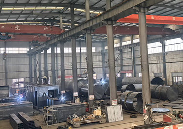 Our FactoryWe have a team of over 30 talented mobile fuel station R&D experts, as well as a 50,000-square-meter advanced modern intelligent manufacturing plant.